
tutorial_1_breadboard_keyboard.md 7.1KB
Tutorial 1 - breadboard keyboard
In this tutorial, you will build a breadboard keyboard with 4 keys. The keyboad will be used in tutorials 2 through 7.
When you finish this tutorial you will have a working keyboard and understand how a key matrix works.
Why a solderless breadboard keyboard is useful
Breadboard keyboards have key matrices and diodes just like the big keyboards.
A breadboard is the easiest way to learn keyboard electronics. Learning is fun when mistakes are easily corrected. Compared to PCBs, breadboard keyboards make learning faster because:
- Mistakes are easily corrected; no soldering and desoldering
- Parts can be reused in many different configurations
- A small keyboard is easier to trouble shoot
Breadboard keyboards are useful for:
- learning keyboard electronics - microcontroller, key matrix, diode, shift registers, I/O expander
- learning the firmware development workflow
- prototyping circuits before making a PCB
Arduino simulation software is an alternative to breadboards; I haven’t tried that.
Breadboard keyboard starter kit
The parts needed to build the tutorial breadboard keyboards are listed in breadboard_keyboard_supplies.ods.
The tutorials use a Teensy LC controller, but any Arduino-compatible controller with at least 2 KB SRAM should work.
You will need two tools:
- Wire cutters
- A multi-meter for trouble shooting
Wire striper, lead-forming tool, and Anti-static mat are optional.
How a breadboard works
To understand the breadboard keyboard you will need to know the internal parts of a breadboard:
- bus strip
- terminal strip
These are explained in How to Use a Breadboard
Electrostatic discharge (ESD) safety
Static electricity can damage a microcontroller in ways that are hard to trouble shoot.
I live in a desert on a carpeted floor and get zapped by door knobs regularly. Whenever I handle microcontrollers I:
- Touch the bare metal on the back of my desktop computer (its grounded).
- Then while still touching to the computer, touch the metal USB connector case on the microcontroller.
Anti-static mat or anti-static wristband are also effective. Being tethered by an anti-static wristband can be inconvenient (wireless antistatic wrist straps are a scam).
Not everyone needs to take ESD precautions:
- http://forum.arduino.cc/index.php?topic=4643.0
- https://forums.adafruit.com/viewtopic.php?f=8&t=12128
Building a basic breadboard keyboard
The basic breadboard keyboard has 4 switches.

A Teensy LC microcontroller is on the left. A key matrix with 4 switches is to the right.
The key matrix has two two columns. Short wires connect terminal strips into matrix columns. Jumper wires connect the columns to the microcontroller.
Two bus strips are used as matrix rows. A jumper connects the top row to the microcontroller. A short wire connects the bottom row to the microcontroller.
Switch-diode pairs, in series, connect rows to columns.
Tutorials 2 and 3 use the basic breadboard keyboard pictured above. Tutorials 4, 5, and 6 will add more components to the basic breadboard keyboard. Positioning components as shown in the picture will provide space for those components.
Breadboard keyboard assembly instructions:
- Bend and cut leads to fit breadboard.
- tactile-switch-lead
- diodes (save the cut offs for steps 2, 3, and tutorial 4)


- Insert parts into the breadboard as shown in the picture.
- The breadboard is oriented with the red bus strips on top and blue bus strips on the bottom (this is important because tutorials will refer to the “red bus” and the “blue bus”)
- Teensy LC is on the left
- switch leads are oriented to connect diodes to columns (pictured below)
- diode cut offs connect terminal strips into columns
- diodes connect switches to blue buses; orient diodes with cathode (banded end) towards the row (bus strip)


- Insert jumper wires to connect Arduino pins to the matrix rows and columns.
- Teensy LC pinout diagram.
- row_0 is the top row, and col_0 is the left column
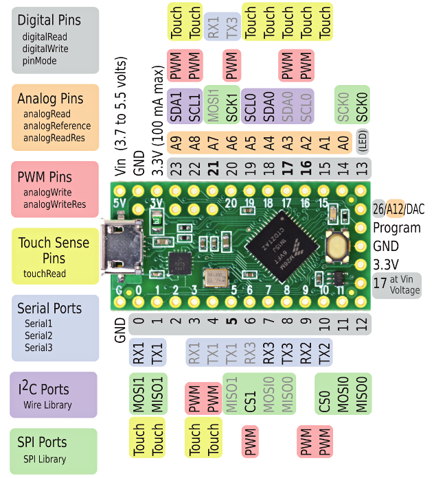
| Pin number | Connects to |
|---|---|
| 0 | row_0 |
| 1 | row_1 |
| 14 | col_0 |
| 15 | col_1 |
Compiling and loading the keyboard firmware
Follow the keybrd Library User’s Guide to set up the Arduino environment.
Compile and load the keybrd_1_breadboard.ino sketch into the keyboard’s controller. The operating system will take 1 to 6 seconds to recognize the USB keyboard. Then pressing the keys should type the characters 1, a, b, c.
How a key matrix works
Congratulations, you have a working breadboard keyboard. Now we fill in some details of how it all works.
This excellent article explains how key matrix, diodes, and ghosting work: How a Key Matrix Work
In the article:
Output pins power columns and input pins detect the power on rows.
The breadboard keyboards in this series of tutorials do it the other way:
Output pins power rows and input pins detect the power on columns.
The keybrd library uses the word “strobe”. Strobe pins are output pins connected to rows. One row at a time is strobed for the purpose of reading input pins.
Exercises
1) replace the diodes with wires (cutoffs) and intentionally cause ghosting.

keybrd tutorial by Wolfram Volpi is licensed under a Creative Commons Attribution 4.0 International License.
Permissions beyond the scope of this license may be available at https://github.com/wolfv6/keybrd/issues/new.