4.8 KiB
Tutorial 5a - indicator LEDs
Keyboards often have LEDs to indicate CapsLock, NumLock, and other states. It's one of the first things we check when a keyboard produces unexpected results.
Adding LEDs to the basic breadboard keyboard
The breadboard keyboard modifies the basic breadboard keyboard described in tutorial_1_breadboard_keyboard.md
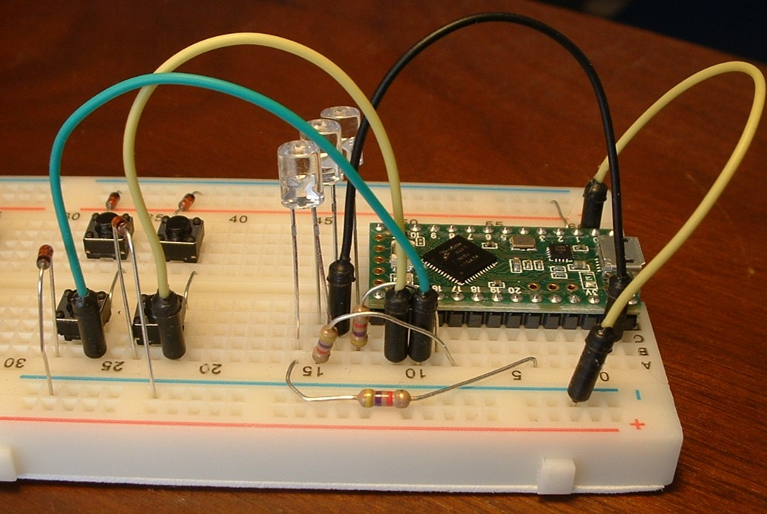
Add components to the breadboard as shown in the picture.
The three clear plastic cylinders are red and yellow LEDs. Each LED is in series with a 4.7k Ohm current limiting resistor. LED anodes (the longer lead) are powered by pins 16, 17, and 21. LED cathodes (the shorter lead) are connected to a grounded terminal strip.
keybrd sketch with LEDs
The keybrd_5a_LED_on_uC.ino sketch will run on the above breadboard keyboard.
LED forward voltage
Forward voltage is the voltage used by the LED. Forward voltage is published in the LED's datasheet.
Most blue and green LEDs have about 3.3 forward voltage, which does not reliably illuminate on Teensy LC's 3.3 volts. Most red and yellow LEDs have around 2.2 forward voltage. So use red and yellow LEDs on Teensy LC. Some low-current LEDs have 1.6 forward voltage.
LED brightness
The amount of current going through an LED is directly proportional to how bright it appears. By picking the correct resistor, you have full control over how bright the LED appears.
Less resistance makes the LED brighter. Too little resistance will burn out the LED. The current supplied to an LED should always be limited by a resistor or some other device.
LED current-limiting resistor values
In the section we will compute the minimum resistor value for maximum LED brightness.
This formula calculates the minimum resistance:
output-pin Supply Voltage   Vs
LED Forward Voltage         Vf
Forward Current             If

From Ohm's Law, minimum current limiting restiance  R = (Vs - Vf) / If
Voltages and current capacities are published in datasheets and sometimes pinout diagrams.
Teensy LC output-pin capacities are:
- four 20 mA pins (5, 16, 17, 21)
- nineteen 5 mA pins
- Teensy LC on-board LED is on pin 13. It has a current-limiting resistor on the board, and does not provide enough power for another LED.
Continuous Forward Current of TT Electronics OVLLx8C7 red or yellow LED is 30 mA.
Plug the numbers into Ohm's Law:
output-pin Supply Voltage           Vs = 3.3 volts
LED Forward Voltage                 Vf = 2.2 volts

For Forward Current, use the smaller of:
current capacity of output pin      If = 20 mA
continuous Forward Current of LED   If = 30 mA

minimum current limiting restiance is  R = (Vs - Vf) / If = 55 Ohms
Add a safety margin for resistor tolerances (1%, 2%, 5%, 10%), and round up to a standard value. http://www.rfcafe.com/references/electrical/resistor-values.htm
55 Ohms + (55 Ohms * 10%) = 60.5 Ohms < 68 Ohms
It is safe to use more resistance.
Calculating the resistance for the Teensy LC 5 mA pin is left as an exercise.
Through-the-hole resistors have color coded bands that indicate resistance value. https://en.wikipedia.org/wiki/Electronic_color_code#Resistor_color-coding
Exercises
- In this exercise you will calculate the minimum current limiting resistance needed for your output pin and LED.
For your microcontroller, find:
- Supply Voltage coming out of the output pins
- Current (mA) capacity of the output pins
From your LED's datasheet, find:
- Forward Voltage
- Continuous Forward Current (mA)
Calculate the minimum resistance needed for your LED and Supply Voltage.
- See how bright an LED can get. In the above breadboard keyboard, replace an LED's 4.7k Ohm resistor with a 68 Ohm resistor. Make sure use a controller pin with a 20mA capacity (Teensy LC pins 16, 17, 21 have a 20mA capacity).

keybrd tutorial by Wolfram Volpi is licensed under a Creative Commons Attribution 4.0 International License.
Permissions beyond the scope of this license may be available at https://github.com/wolfv6/keybrd/issues/new.
